


and PCB Chassis
by Phil Wicks
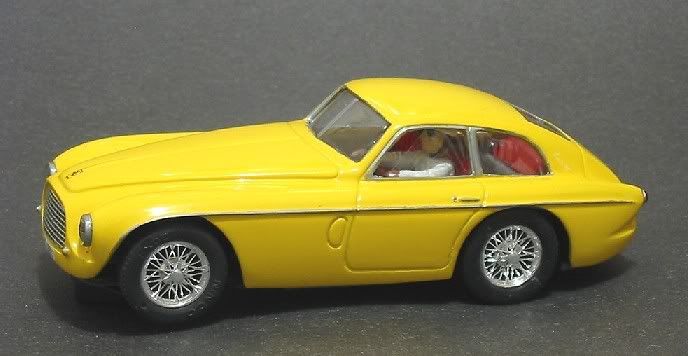
After a recent local race meeting I was impressed by a Ninco Ferrari 166 MM in the Classic Sports car event. Further research showed Ninco Ferrari 166’s to be a bit collectable and as a consequence a bit pricey too! Still, not to be deterred I typed in the relevant details into a search engine and sure enough there was a plethora of Ninco Ferraris available but all without exception were at a price.
A bit further back through the search finds was a link to the Ocar Ferrari 166, A model I had been aware of but not that aware that it would spring to mind. The solution was at hand, albeit a resin body, but a 166 none the less. So after checking out the eBay stores, sure enough, John from Classic slot had a body kit listed.
Feeling bit flush, I decided to order it and after six days or so it was waiting for me when I got home from a hard day’s work. I must admit to having a bit of trepidation regarding resin bodies in the past but once you have the measure of them a whole new world of scratch building opens up to you. This model was no exception and very soon I was putting off important social engagements so I could be at home with my 166, working diligently and painstakingly putting it together piece by piece. This was going to be my best model yet!!

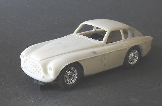
The Ocar resin bodies are quite good by comparative standards and the details is fair and most importantly the bodies are fairly square! Most resin bodies suffer from distortion in the production process for one reason or another. They can also become deformed if not properly packed for postage. Part of the cause is the composition of the resin itself. Two pack resin is normally clear or semi opaque and consequently more brittle than one would like but the Ocar bodies have a fine fibrous additive in the resin which toughens them up to an acceptable level.
The bodies look like they are also made by the swirl method. This means the blank mould has a quantity of resin poured in and the mould is tipped and rotated until all parts are covered. This may be repeated two or three times. The end result is a sturdy but heavy body which has certain unevenness about the depth of resin. But don’t let this deter you; there is a simple solution, trust me.
If you hold the body up to a strong light source like an angle poise lamp or similar, you can see the thickness of resin in the shades of light penetrating the body! It is a simple job then to dremel the darkest areas with a ball type bit until they allow a similar shade of light through the body to the lighter places. Another guide is to do one side first. It is then easy to gauge the thickness with a forefinger and thumb. Once you have done this to one side, the rest of the model is ground back with the dremel bit til its lightness matches the side you are happy with. Check the model with the lamp regularly and as you approach your optimum thickness back off a bit and use shorter and shorter strokes. The door and bonnet seams won’t be too far away and a little over zealousness will see you cut through to a seam. Not a big deal but it will then be extra work to refill it.
I use the flexi drive on my dremel and with a medium diamond ball bit; I sweep quickly across the panel I am lightening diagonally, much like when you shade in a drawing with a pencil. I then do it from the opposite diagonal direction, going back and forth, testing at the lamp, until I am happy with the body. This is to minimise the risk of ridges and valleys forming. You should end up with a fairly even cross hatched area. It should now have lost a good deal of excess weight, consequently allowing you to shift the C of G lower down in the model without a massive weight increase. On this model, the starting weight was 24 grams for the bare body and by the time I had removed the mounting points and thinned the whole body to an even shade, I had reduced it to 16 grams. A saving of 33% I can add lower down as constructive ballast if I need. I also consider I have not impaired its robustness and fully expect the model to remain resilient.
If you have a body which is a little out of shape, it may well be a storage or packing injury. It is quite alright to heat the body up with hot water and then applying moderate pressure to return it to its position BEFORE you start lightening it. It will stay there too when it cools
One cautionary note – DO NOT grind down the roof posts. The weight saving will be negligible but the roof mounting could be severely compromised if you go too far! These will have a very light trim to aid window fitting at a later stage.
The Chassis
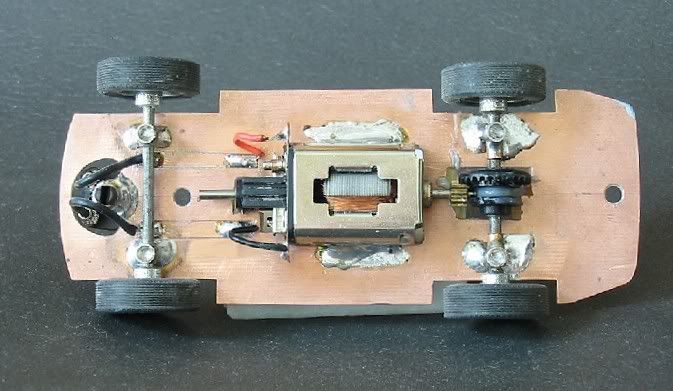
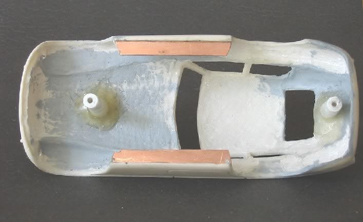
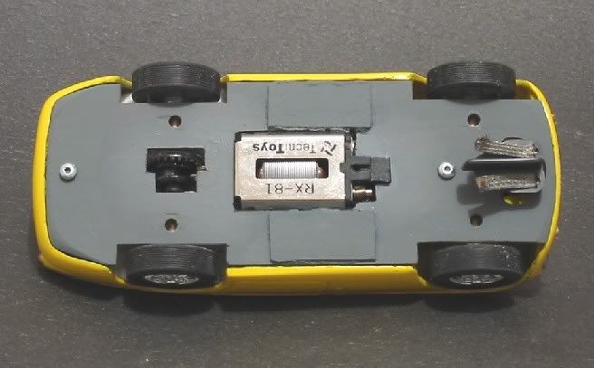
The chassis is the now familiar ‘Wixwacing’ circuit board chassis with a ‘Wixle’ front end, Ninco sprung guide and Ninco Classic wheels and tyres all round. With the body ready for painting almost, it is necessary to get all the other parts finished and in trim. We don’t want to be making alterations to a painted body! So, the chassis plate is cut from a piece of PCB and formed to shape so it will fit snugly inside the lower body all the way round. As this will be a ‘two screw’ chassis it will be necessary to fit some kind of travel limiting device to the body so the body doesn’t flop about uncontrollably. For this I used two thin strips of PCB which have been glued to the inner sides of the body and which will hold the chassis flush with the bottom of the body when at rest. These pieces are held in by a couple of spots of superglue initially and are epoxied in place when I am happy with their position.
Once this is done, the front and rear axle positions are marked on the copper with a pencil and when happy, these lines are scribed into the copper surface for permanency. The front and rear axle mounting post holes are marked and pilot drilled with a 1/16 drill bit. The rears and fronts are then drilled to the tube diameter and the rear axle and contrate are mounted in the tubes and pressed into the board. The cut out for the contrate is marked with a pencil and the axle removed. The cut out is then ‘cut out’ using a dremel and a cut off disc. Using it edgeways-on allows you to get a radius in the board for the crown to fit into. The wheels are temporarily pushed on and the body laid over the chassis. The mounts are moved up and down until the ideal spot for the wheels is obtained. The chassis is carefully removed and the motor offered on to the chassis and a line drawn around all four sides at the PCB contact area. The rectangular hole is then cut out with a dremel and cutting disc and the motor offered up. The motor hole is then carefully filed until the motor sits through the chassis in correct mesh with the crown wheel and with the armature shaft intersecting the centre line of the axle.
The guide needs to be mounted next. This will sit in a brass tube cut to length. To do this I mark the centre point for the guide and using a plastic circle template, I mark a 17 m.m. diameter circle concentric to the mark. The hole for the guide tube is marked and drilled out to the tube diameter. Next, the curved slot for the lead wires is drawn in and using a drill bit, I remove the bulk of the waste then trim up with a curved modellers file. This slot will also be the guide stop so it only goes just half way round the tube. Enough to give the guide plenty of movement. I prefer to use hand tools and not the dremel for this and other fine work as there is less likelihood of overdoing it and then having to repair a gashed slot.
If the axle mounts haven’t moved at all and you are happy with them they can be marked and soldered into position. The motor can then be soldered into place too. And finally the guide tube is soldered in place. This gives you your completed chassis with only a few minor things left to do on it. The focus is turned to the chassis fitting in the body. I wanted to mount the body by two screws as opposed to the four screw mountings of some of my earlier models. First handicap was that I removed the mounting posts. These had to go. They were very rough and were next to useless. The solution to this dilemma was easy. I have some plastic tube in varying slide fit diameters and it just so happens that the smaller tube has an ideal diameter hole through it to take a 2 gauge screw.

The chassis was positioned and using a depth gauge, I measured the distance to the body directly through the pre drilled screw holes. Once the distance was established, three lengths of plastic tube were glued and ‘telescoped’ into each other creating a very sturdy post. The end of the tube was squared and a thread tapped into it using a body screw. The two posts were then cut to length according to the depth gauge measurement and the end of each was suitably profiled to match the body contour at point of contact. After a day or so drying, the posts were then screwed to the chassis and the chassis offered into the body. Once the posts were the correct length their bases were scored radially with the tip of a modeller’s knife and where they contacted, the body was scored by cross hatching in two directions. Slow drying epoxy was then mixed and applied to the body end of the posts and the body cross hatching. The chassis with posts attached was then placed into the upturned body and the epoxy was allowed to merge. Twenty four hours later the screws were removed to reveal the two posts firmly in position. I then mixed a little more epoxy and reinforced the two glued joints and left for a further 24 hours.
At this stage I did some fine tuning to the inner wheel arches. The arches are quite thick and to cut the axles to suit these would see the wheels unrealistically tucked away inside the body. Some judicious dremelling with a ball tool was needed to take out the wheel curve in the inner arch material. Eventually, without compromising the strength of the arches I managed to mount the wheels within a half millimetre of the outer arch giving the model its maximum axle width front and rear. We now have the completed chassis fitting the body. I did in actual fact run the bare model at this stage to ensure there was no extra work I had overlooked before painting. After running it for quite a while at a friends board track I passed it as sound and on returning home made plans to finish the body.
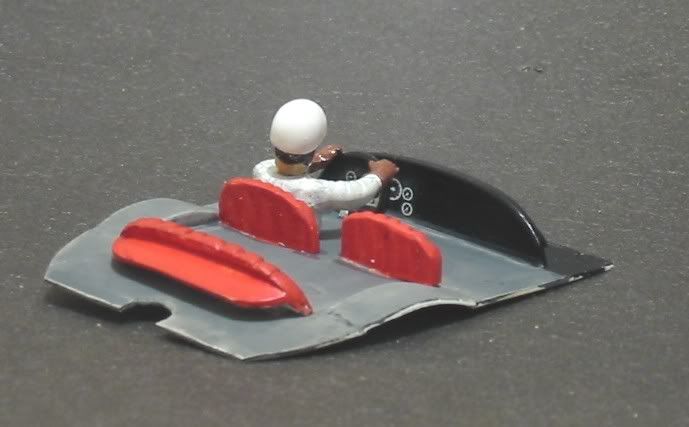
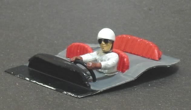
Before continuing with the body exterior, there was still the matter of the interior. The model comes with a very presentable vacuum formed interior but its fit is a little harder to manage so I made a new drivers tray from plastic card as I have always done. The dash was laminated and shaped and the front and rear seat backs were shaped. The whole was offered up time and again until I was happy with the fit and then the parts were glued together. The driver was painted and glued into his seat along with steering wheel and dash board. This was offered up regularly too to make sure it was all going to fit on final assembly. Although it wasn’t to be glued in place it needed to be a snug fit once in. All the driver’s tray parts were painted appropriately. I had some gauge decals left over from a Vanwall job I did a long while back and these look totally effective on the 166’s dash. I also found a resin head with an early crash helmet. I sculpted the crash hat till it looked like a ‘pudding basin’ and then set about changing the driver’s goggles to look like a pair of sun glasses. The seat backs were made from laminated plastic card and I have tried to make them look like the leather quilted seats that were popular in the fifties. The steering wheel also came from the scrap box.
The body had a few minor pin holes which would have been air in the moulding. This filled adequately with Tamiya body putty. Another pre paint repair was the left hand rear wheel arch which was bigger than the right and a little further back. Using a modellers file I moved the arch front forward and closed in the rear of the arch with the putty. A light sand with 600 grit paper and the first coat of primer was applied. This revealed another multitude of sins but again, not heartbreakers and with the aid of the Tamiya putty the last major blemishes were repaired. The models ‘Monza’ style fuel cap had a large air bubble in it and I was prepared to cut it off and fit another from the spares box but I did fill it and after some deft handiwork with a sharp modeller’s knife it looked good so I left it on. The body then had its second coat of flat lemon yellow and it’s last round of touch ups.
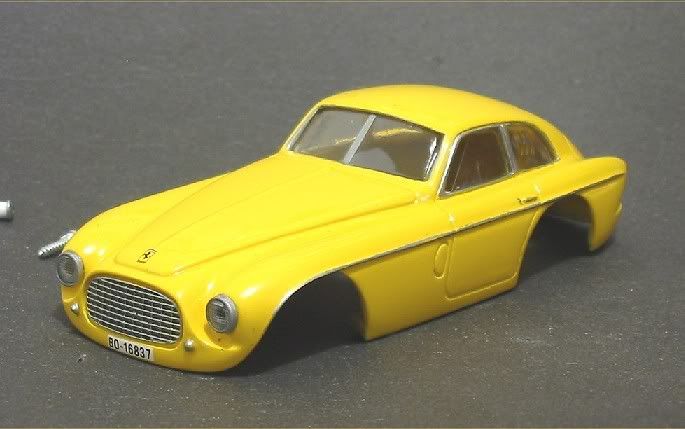
The areas around the rear side windows are a bit ambiguous and undefined and looked to be a lot more difficult to change so I left them as they were and decided to do an ‘optical’ repair. That was, to paint a chrome window frame around them to give the impression of a window/body joint. Next stage was the first gloss coat. Tamiya Lemon Yellow. Too many of my Ferraris are red and after a contributor showed pictures of his resin 166 in yellow I couldn’t help myself! So the first gloss was on. A very light sand to remove dust specs and then the second coat. After a period of a coupler of days I gave the model its first coat of clear. The tail lights were painted all over with silver. Once dry, I then painted the rear light lenses with ‘clear red’ from Tamiya. When the clear coats go on, this will look quite effective. The body colour was very solid now and before anything else it was time for the chrome parts.
I have used ‘Baremetal’ foil on other models to get a lifelike chromium sheen with great success but the grille on this model, plus the door handles and waist mouldings, not to mention the window frames, were asking just a bit too much of it. I decided on an aerosol pack of ‘Silver Chrome’ from the local auto store, still like a metallic grey but a lot more realistic than some of the silver paints I have used. This was shaken well and some sprayed into an old clean Tamiya paint jar. I then proceeded to hand paint all things chrome. A steady hand was required but in the event of a painting fault, because I was painting onto a clear coat, I could use a piece of 1200 wet and dry superglued to a small piece of flat brass as an eraser. When all the silver was painted and dried for a couple of days I carefully went round the poorer edges and using a lot of water, sanded off the painting errors!! This way I could get a sharper edge to fine lines without rubbing through the colour coats. The decal number plates and Ferrari badges where then applied and after another drying period the whole model had a thinned coat of clear. Again, once this had dried for twenty four hours I sanded the model with 1200 and gave it one more clear coat and left it to dry for a few days.

Now we are getting close to finishing!! The windows came as a single vac formed piece but for various reasons to use it as such wasn’t going to happen. The four glasses were cut from each other and trimmed to remove the excess lip around them. This was all done before painting as continual handling of the body at this stage would surely mark the paint job. Now, with four frail looking pieces of clear plastic it was time to fix them one at a time Mmmmm!
The clear parts were trimmed to fit the window openings and to have about a three millimetre overlap on the inside. This was to give me enough room to put some tabs of superglue to initially fix them and later, enough room to epoxy them in. Both front windows were trimmed to give them that open look. So, the back window was put in place and with a small spot of superglue on the end of a modelling knife I put a spot under a corner of the clear and held it in place for twenty seconds or so with the pencil sharpened end of a piece of 6 mm (1/4â€) wooden dowel. I then proceeded to do the other three corners. The same operation was carried out on all the clear pieces and some of the longer bits had an extra spot on the sides. I had already tested the super clue on an off cut as it can cloud some plastics. In this case, all was ok.
Next was the permanent fixture. A small amount of epoxy resin was mixed and the edges of the clear panels were ‘painted’ with epoxy! This was done with a fine brush and care was taken to make sure the epoxy lapped over the edge of the screens to ensure a durable fix. The brush was later cleaned out with brake fluid and then rinsed in water. Note!! Don’t forget to clean the clear parts before fitting and try to avoid handling them! I used a small pair of tweezers quite successfully. Allow this lot to set for three or four days. Sometimes epoxy can feel ‘tacky’ for a bit and we want to avoid dobbing an epoxy finger print on the inside of the clear parts don’t we!!
Once the windows were set the interior was tested in place and a few minor trimming adjustments were made to accommodate the new clear glass pieces. The driver’s tray was slid in to make sure it was a good fit. Once all was well the body had its last coat of clear, including the windows. (The clear of the vacuum formed windows sometimes looks a little cloudy so a coat of clear smoothes out the dimples and defects to give the glass a clear effect). A very light sand first with 1200 grit to take off any specks and the final coat was thinned to a fairly fluid consistency and tested on a piece of scrap to gauge how easily it would run. Once the last coat was applied the body was rotated slowly on its stick for a couple of minutes. This ensured there was minimum risk of runs in what was going to be a glass like finish.
Well, a few months in the making but well wort it. A couple of minor defects. One being in the manufacturing process (rear side windows) and the other in my finishing technique and the model is ready for the track. I’ll give it another week before I run it as it has had a lot of paint and the first week or two it will be vulnerable. But it will be fine after that!!
So, what is it like well, I’m very pleased. The model is well powered by the SCX motor and at the same time the motor spreads its weight across the chassis creating a very well balanced model. I was suspecting it might show some top heavy traits but far from it! The body lightening with the dremel has made it as light, if not lighter than a comparable plastic model. The model has an all up weighs 91.0 grams including about 8 grams of ballast under the chassis. The front carries 40.0 grams and the rear 51.0 grams. Giving it a 44% / 56% split. It will take off smartly on the Ninco 21 x 7 classic tyres and they will let go a bit in corners and allow the model to drift very nicely around even the tightest of bends. Once round the bend the model will pull away sharply and hit top end quite comfortably without drama or incident.
Well, I don’t know. Do I have to get another race box and carry them BOTH around with me!! I get attached to the scratchbuilt models I make and I always have several in my race box and when I visit other tracks I take the opportunity to run them and decide on what adjustments will need to be made.